
D-Geo Pipeline - Micro Tunnelling module
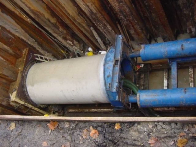
Micro tunnelling is the technique which uses a tunnelling machine to remove the soil. Micro tunnelling usually starts horizontal at a certain level below the surface.
Start and reception shafts are created for the micro tunnelling machine. In the start shaft a jacking frame and micro tunnelling machine are installed in front of the pipe sections. The jacks push the pipe elements section by section ahead towards the reception shaft. As the length of the advancing micro tunnel increases, the friction forces will increase. Lubrication fluid may be applied to reduce the friction. Very often, drilling fluid is used for soil removal and face stabilization at the front of the micro tunnelling machine.
Features
- Drained and undrained behaviour of soil layers
- Graphical output of calculated face support pressures, trust forces and subsidence through
- Calculation of settlement of the soil layers below the pipeline
Face support pressures
The micro tunnelling machine changes the stress conditions in the soil. The deviations from the original stress conditions are largely determined by the size of the overcut and the applied shield. Small deviations from the original conditions are acceptable as long as the stability of soil adjacent to the micro tunnelling machine is maintained.
A relatively low face support pressure may lead to collapse in front of the shield, which in turn may lead to subsidence of the surface or to settlement of soil layers below a construction or pipeline. A relatively high face support pressure can lead to a blow out of drilling fluid or may lead to surface heave.
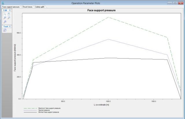
While drilling, the shield pressures have to be kept between certain limits. To prevent the possibility of collapse of the soil in front of the micro tunnelling shield, causing subsidence, the soil at the front is kept stable by maintaining a minimal face pressure. Depending on the soil type the minimal support pressure can be calculated using Jansecez and Steiner theory, or Broms and Bennermark theory.
A maximum support pressure should not be exceeded to prevent uplift of the soil above the micro tunnelling machine or a blow out of drilling fluid towards the surface. The support pressure, the target pressure during drilling, should be in between the two limits. At the neutral pressure, the face support pressure is in equilibrium with the current horizontal soil pressure.
Thrust force
The micro tunnelling machine is at the front of the advancing pipe sections. As the length of the advancing micro tunnel increases, the friction forces along the micro tunnelling machine and the pipe segments rises. Lubrication fluid may be applied to reduce the friction. D-Geo Pipeline compares the predicted thrust force with the maximum allowable thrust force.
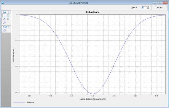
Surface subsidence
During the micro tunnelling drilling process the volume of removed soil is generally larger than the volume of the micro tunnel or pipeline (overcut). The volume difference will lead to soil movement towards the borehole, which in turn will lead to surface subsidence (trough) is calculated and graphically shown by D-Geo Pipeline.
The Micro Tunneling module is available as the D-Geo Pipeline Micro Tunneling package. For more information, see D-Geo Pipeline Service Packages.