
D-Sheet Piling - FAQ and Known Issues
Find all of the known issues and frequently askes questions concerning D-Sheet Piling on this page.
Known issues
Solved in 23.1.1: When using the option "Initial stage represents initial situation" the neutral earth pressure coefficient may be incorrectly calculated in subsequent stages (MSH-4637)
The load correction Sigma_h;correction, as indicated in the manual (equations 36.4 and 36.5), is calculated correctly in the initial stage. However, when calculating the neutral earth pressure coefficient in the following stages, an incorrect value of Sigma_h;correction is used if the ground level in this stage is different from the initial stage.
Solved in 23.1.1: For EC7-NL/CUR verification, the phreatic line at passive side is not always decreased (MSH-4616)
For steps 6.3 and 6.4 of a EC7-NL or CUR verification, the phreatic line at passive side is not decreased when the phreatic line is above or coincide with the top of the wall. This is not correct, the phreatic line at passive side should be always decreased.
Solved in 23.1.1: Reliability Analysis: Detailed stage results in Report are based upon incorrect design values (MSH-4532)
In the Report displayed after a Reliability Analysis, the detailed stage results given in chapters “Construction Stage …” are based upon the design values determined during the second to last iteration, instead of the design values as given in section “Reliability Analysis Results” of the Summary chapter (which are the design values determined during the last probabilistic iteration).
Solved in 22.1: The max value in the Summary of the Report is incorrect for vertical balance (MSH-3802)
When the calculation for the vertical balance for all phases and tests is ‘sufficient’, the max may be incorrectly displayed in the report as ‘not sufficient’. The calculation for all stages and tests is correct and the max is determined incorrectly in this case, it should display “sufficient” when all stages and tests are also sufficient.
Solved in 22.1: No validation error is displayed when the Ka,Ko,Kp method is used with surcharge load or non-horizontal surface (MSH-3889)
A surcharge load or a non-horizontal surface are not allowed in combination with the Ka,Ko,Kp method. This is one of the limitation of this method. However, since version 19.2.1, this combination is by mistake allowed and does not lead to a validation error message before the calculation.
However, the effect of the surcharge load or the non-horizontal surface is not taken into account during the calculation.
Solved in 20.2.1: For the Vertical Balance check in combination with a verification calculation, no partial factor is applied on the normal force (MSH-3661)
For the Vertical Balance check in combination with a verification calculation, no partial factor is applied on the normal force. But the partial factor defined in the User Defined Partial Factor window under Factors on loads should be applied.
Solved in 19.3.2: Incorrect anchor force for step 9.1 of EC7-NL or CUR (method A) if several anchors are present (MSH-3564)
If several anchors are present during a verification calculation according to EC7-NL or CUR with method A, the determination of the maximum anchor force in step 9.1 is based on the same CUR step (between 6.1, 6.2, 6.3, 6.4 and 6.5 times factor) for all anchors whereas this step should be determined per anchor.
Solved in 19.3.2: Incorrect inputted moment given in the Report for a Single Pile calculation (MSH-3577)
The value of the inputted moment given in the Report after a Single Pile calculation (under chapter Input Data, paragraph Moments, in kNm) is incorrect: it is the inputted moment divided by the diameter of the pile but it should be just the inputted value.
Solved in 19.3.2: The default value of the modification factor of the sheet piling is incorrect when a new project is created (MSH-3572)
When a new project is created, the first section in the ‘Sheet Piling’ window is by default set to ‘Steel’, but the modification factor is set to 0.50, whereas a modification factor of 1.00 is expected.
Workaround: the material type can be temporarily set to ‘User Defined’. After the material type is set back to ‘Steel’, the correct modification factor is used.
Please note that the correct modification factor is used when the option ‘Import profile from the library’ is used.
Solved in 19.3.2: In the summary of the Report, results from the same support is listed multiple times (MSH-3570)
When a calculation is performed with multiple supports, the summary of the Report displays the values only from the first support but multiple times.
Workaround: In the Calculation Results later on in the Report, the values for the other supports are listed.
Solved in 19.3.1: Incorrect pictures displayed in the Report after a Verification calculation with method B (MSH-3476)
In the Raport, after a Verification calculation with method B where only some stages are verified, incorrect pictures (for Moments, Forces, Displacements and Outline) are displayed (either empty pictures or pictures corresponding to another stage or calculation step).
Workaround: perform the verification for all stages by selecting all of them.
Solved in 19.3.1: After creating a sheet piling using the Combi-wand wizard, an incorrect modification factor is used (MSH-3500)
When creating a sheet piling using the Combi-wand wizard using steel and/or concrete materials, the modification factor used is always 0.5 instead of 1. This leads therefore to an incorrect value of the design allowable moment Mr;d.
Workaround: Change the material type to ‘User-defined’, go to another cell of the table and then select again the original material type (‘Steel’ or ‘Concrete) ‘.
Solved in 19.3.1: Factor on moment(s) is not applied correctly for a verification calculation with CUR/EC7-NL and method B (MSH-3408)
For each CUR step calculation (6.1 to 6.5), the moment is multiplied with the corresponding safety factor. After each CUR step calculation, the moment should be reset to its original value (without factor) before applying the safety factor corresponding to the next CUR step. However, the reset is not performed leading to very high (and incorrect) values of the moment.
Solved in 19.3.1: Factor on horizontal line loads is not applied correctly for a verification calculation with method B (MSH-3432)
For each CUR step calculation (6.1 to 6.5), the horizontal line load is multiplied with the corresponding safety factor. After each CUR step calculation, the horizontal line load should be reset to its original value (without factor) before applying the safety factor corresponding to the next CUR step. However, the reset is not performed correctly leading to incorrect values of the horizontal line load.
Solved in 19.3.1: Access violation when opening the Stress Diagrams window when a Verify Sheet Piling - Method B is performed with not all stages calculated (MSH-3411)
Solved in 19.3.1: For Vertical Balance check, in the Report, the contribution of the vertical balance per layer is always 0 (MSH-3417)
The vertical balance check is performed for the models Sheet piling and Diaphragm wall in the Model window. The input values are defined in the Sheet Piling window.
After a calculation is finished, unexpected results are found in report in the section ‘Vertical Force Balance – Contribution per Layer’. In this section, the contribution for both the left as well as the right are set to zero.
For version 19.1 the correct results are displayed in the report. We aim to solve this issue in the next release.
Solved in 19.3.1: Incorrect result when a spring and a rigid support are defined at the same level in a stage (MSH-3404)
When a spring and a rigid support are defined at the same level, no validation error of the input is displayed but this combination is not allowed because the program doesn’t know which values he has to use.
Workaround: make sure that a rigid and a spring support are not defined at the same level in a stage.
Solved in 19.3.1: The calculation of a Single Pile loaded by calculated soil displacements gives incorrect results in version 19.1 and 19.2 (MSH-3544)
Since version 19.1, the moments / forces / displacements calculated for a Single Pile loaded by calculated displacements are incorrect. They include by mistake the extra horizontal stresses due to the surcharge load (according to Boussinesq theory). The results of the moments/forces/displacements are therefore overestimated.
Solved in 19.3.1: For a Verify calculation with EC7-NL, step 9.1 (anchor force) can give an incorrect value in some cases (MSH-3434)
If the decisive step (between steps 6.1 to 6.4 and step 6.5 * factor) for the calculation of step 9.1 is step 6.5 * factor and if the factor on representative values is not 1.2, then an incorrect factor is used for step 9.1 (always 1.2 instead of the user-defined factor).
Frequently Asked Questions FAQ
When performing a vertical balance check on a combined wall, I get unexpected resultsIs it possible to model a pile with the Sheet Piling model?
The vertical balance is not suitable for combined walls. It can not be separated out what is the point of resistance for the upper part. Calculations are based on the point resistance of the bottom part; point the resistance of the upper portion is not taken into consideration.
Is it possible to model a pile with the Sheet Piling model?
In some cases (eg none-horizontal ground surface), the Single Pile model can not be used to model a pile. In such a case, the Sheet Piling model can be used to model a pile by:
- entering the stiffness EI [in kNm2], the maximum moment Mmax [in kNm] and the section modulus W [in cm3] divided by the pile diameter (because with the Sheet Piling model EI, Mmax and W must be entered respectively in kNm2/m ‘, kNm/m and cm3/m’)
- entering the pile diameter as acting width
- entering a shell factor to multiply the passive earth pressure coefficient Kp and the modulus of subgrade reaction k and to divide the active earth pressure coefficient Ka by this shell factor. Note that Kp and k (resp. Ka) are automatically increased (resp. decreased) by the program with the shell factor
- entering a pile force in kN divided by the pile diameter (because with the Sheet Piling model, the horizontal force must be entered in kN/m’).
To what extent is D-Sheet Piling suitable to perform an undrained calculation for a layered soil with cohesive properties?
Undrained calculation is not directly available as a special option in D-Sheet Piling; but it can be simulated using phi = 0 and c = cu and moreover by adjusting the water pressures. The user has to calculate or estimate himself the under/over stresses and enter them in the program.
Why do results for modelling for under water concrete provides unusual results?
Calculating the vertical force balance (also under the CUR design code), it is of importance which side is passive, as the direction of the vertical force is upward on the passive side. Whether or not the side is passive is determined based on the which side has the largest percentage of soil mobilized. If one is modeling for under water concrete, the high strength of the material may incorrectly results in the assumption of a passive opposite side. If one is modeling using CUR design code, the lowering of the active side may have a likewise effect. This should be overruled within the stage overview by indicating which side is passive.
CUR or EC7-NL verification: Why does Step 9.1 does not appear as a separate paragraph in the report?
If an anchor stiffness multiplication factor unequal to1 is used, step 9.1 of the CUR applies. Step 9.1 (Anchor verification) has no separate paragraph anymore. This step is reflected in the summary and the pictures in the beginning of the report. In the separate paragraph only the different anchor load was of interest, but this is already covered by the summary. The moments and forces as displayed in the paragraph step 9.1 are not relevant for the CUR check. For these reasons it was decided to remove the paragraph for version 7.9.1.5 onward.
CUR or EC7-NL verification: Why are steps 6.1 and 6.2 are not always calculated?
In step 6.1 and 6.2 the phreatic level on the passive side is increased. This can be unfavourable when the phreatic level is below surface. When the phreatic level is upon or above the surface an increase is always favourable. Therefor steps 6.1 and 6.2 are not calculated.
What does the option "Reduce delta friction angles according to CUR" do?
CUR 166 states that for rough steel walls or comparable walls, the calculation of the passive earth pressure coefficient may be based on straight slip planes, provided that delta is a maximum of 30 degrees. For a rough concrete surface, a maximum delta of 35 degrees applies. For higher values, curved or angled slip planes must be used for the calculation.
The reason for this is that straight slip planes give values that are too optimistic for the passive earth pressure coefficient and that the value in the case of an increasing resistant strength will start deviating from the value determined with curved slip planes. This occurs even if, as is usual, calculations are made with a lower wall friction angle for straight slip planes.
In Table 1, Columns 2 and 3, a comparison is made between curved and straight slip planes, based on a rough wall surface. In the fourth column, the passive earth pressure coefficient is calculated for a straight slip plane with reduced wall friction angle. It has been reduced in such a way that the passive earth pressure coefficient matches that of a straight slip plane. The angle used is displayed in Column 5.
Passive earth pressure coefficient p
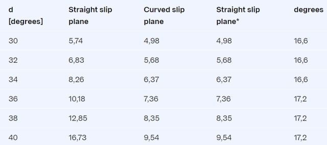
Straight slip plane : Calculated with = 2/3*
Curved slip plane : Calculated with = -2.5 with a maximum of 27.5 degrees. Formulas of Caquot-Kérisel
Straight slip plane *: Calculated with the (reduced angle) from Column 5.
When calculating using the (c,phi,delta) method (straight slip planes), the value should be reduced to the value in Column 5. The reduction applies to steel walls with a delta larger then 30 degrees and rough concrete walls with a delta larger then 35 degrees.
Why has my anchor only a plate below the anchor rod?
In the D-Sheet Piling user interface only the anchor plate is drawn below the anchor rod. Only the distance rod-bottom anchor plate is entered in the user interface. For the Kranz stability this distance is required; in the calculations it is assumed that the plate runs up to the surface. For the reasons above it was decided to only draw the lower halve of the anchor plate.
CUR or EC7-NL verification: Why is the maximum value for an anchor/strut not always displayed in the report summary "Anchors and Struts"?
When method A is used, D-Sheet Piling determines the highest anchor force over all stages and verification steps (6.1-6.5). The verification of the anchor force is made with the verification step with the highest anchor force.
A verification with method B shows a slightly different result, because for each stage the verification step with the highest anchor force is selected.
If multiple anchors are present, both methods do the verification using the same step.
What is meant by “acting width”?
The D-Sheet Piling manual contains the differential comparison used by D-Sheet Piling:
b.d2/dx2.EI.d2w/dx2 + d/dx.N.dw/dx = b.f(x,w)
Where b is the acting width. This is the width of the soil that is pressing against the pile or wall. The EI must be specified for each acting width.
For a sheet-pile wall, the calculation is actually performed using a standard acting width of 1m. The EI that is specified is therefore the EI of 1m of wall. The results are also per acting width – that is, per 1m.
For piles, calculations are often made with an acting width other than 1m. For example if the pile is 0.5m wide, and the width of the soil pressing against it is 1.5m, the acting width is 1.5m. The EI of the pile must then be divided by 1.5m. This models a situation in which 1.5m of soil is pressing against a pile of 0.5m.
Another use is for constructions such as combi-walls and Berliner walls, where the acting width changes over the depth. See for example manual, tutorial “Modelling of combi-walls”.
Why does the results of a ‘Design Sheet Piling Length’ calculation differ from a usual calculation?
Assuming that the ‘Representative’ class has been used with ‘Design Sheet Piling Length’, it may be that the ‘Manual’ option is active. In that case the earth pressure coefficients are not recalculated but are extracted from a file.
Notice that when a safety class is chosen, under the Design option not a complete verification will be made. This requires the Verification option.
What is the difference between 'fine' and 'coarse' in the calculation options?
In D-Sheet Piling the earth pressure coefficients are calculated for each element. On the elements intermediate nodes are placed. These nodes use the earth pressure coefficients of the element, this is the ‘coarse’ option.
For the option ‘first stage represents initial situation’ it was found that the earth pressure coefficients had to be determined at the intermediate nodes otherwise installation with neutral stresses at both sides was not correctly modeled, this is the ‘fine’ option. However this means that five times more earth pressure coefficients are calculated compared to when using the ‘coarse’ option, so the calculation time is significantly longer.
The results of both methods may differ. These differences occur mostly at slopes or loads close to the sheet piling. In these cases the ‘fine’ option is recommended, in other cases faster calculations can be made using the ‘coarse’ option.
Why do I see support forces that were not introduced in the project?
D-Sheet Piling calculates support reactions for each node based on equilibrium considerations for every phase. Support reactions larger than a certain value are reported. However, in some cases there are support reactions in nodes where the user did not introduce a support. In these cases, the magnitude of the support reaction is a measure of a certain error made in the calculation as the basic equation for the sheet pile wall assumed relatively small deformations and bending. When the deformations and bending become larger, extra forces and moments are introduced in the calculation to try to satisfy the basic equation. You can consider the calculation to be accurate enough when these values are small compared to the actual forces and moments. However, when these values are relatively large the sheet pile wall will not react according to the assumption of the basic equation anymore. In that case the deformations will often be unacceptable in practice. Unintentional support reactions can also occur when there is a large difference in stiffness between neighbouring elements.
Why is it that after adding construction phases or anchors, the answers for the unchanged construction phases also change (somewhat)?
D-Sheet Piling creates nodes on all supports and layer boundaries. If an anchor is added, for example, the total node layout (even in the phases where nothing changes) may be adjusted. This can result in small differences in the outcomes.
How are (prestressed) anchors implemented?
- Anchors:
The wall can be supported by one or more anchors, either prestressed or not. In successive phases, it is possible to remove or introduce anchors, or to modify the prestressing force. The size of the anchor force is executed at the end of every phase. - Non-prestressed anchor:
The non-prestressed anchor is considered to be a spring support. The flow force that is specified applies as the upper limit of the anchor force. The lower limit has the value 0, so that no compression can occur in the anchor. After flow, hysteresis is taken into account. - Prestressed anchor:
The load from the wall as a consequence of a prestressed anchor is considered to be a point load the size of the specified prestressing force.
When the prestressing force is specified for an anchor, the resulting anchor force is equal to the specified prestressing force. This can be modified for each phase. When a prestressing force specified earlier is omitted in a subsequent phase, the anchor is considered to be just a spring support (see ‘Non-prestressed anchors’ above). The program does assume, however, that the prestressing force will be maintained. The total anchor force is then equal to the prestressing force, increased or reduced by the force caused in the anchor by the extra displacement in the relevant phase.
Why is the passive resistance calculated with delta=2/3 * phi, where according to the Spundwand Handbuch delta=0 should be applied at the location of horizontal anchorage by an anchor plate?
The deltas specified together with the soil characteristics are applied. For an anchor plate, a delta greater than 0 may in principle be used if that delta satisfies the vertical equilibrium. If not, the delta with the soil characteristics must be adapted.
Minor alterations in the input give rise to major differences in the outcome. Why is this?
This can occur if the calculation process does not converge properly. In the report of the calculation, this is reflected in the number of iterations required for the calculation. Approximately six iterations are quite normal, but if the number exceeds ten, this indicates an improper calculation result. One of the causes can be a small ratio between the rigidity of the sheet-pile wall and the modulus of subgrade reaction. This problem can be solved by using a more rigid sheet-pile wall.
Why is the horizontal button bar not displayed In the ‘Design Sheet Piling Length’, ‘Verify Sheet Piling’ and ‘Characteristic Kranz Anchor Strength’ windows?
This is an error in D-Sheet Piling that occurs only with the Windows setting ‘Large Fonts’. The easiest way to solve this is to choose to use ‘Small Fonts’. However, if you want to continue working with ‘Large Fonts’, you can operate the buttons using the keyboard by pressing the key combinations: Alt+S for Start, Alt+C for Close and Alt+P for Print. You can also use the arrow keys (up and down) to select another construction phase.
Why do I have problems reading DXF exported files in Autocad?
The option to export pictures in DXF format was developed for, and tested with, AutoCad 14. In more recent releases of AutoCad something has changed in relation to the import of DXF files. This means that these versions do not read our DXF files properly (detected by us in versions 2005 and 2006). The majority of viewers, for instance “Bentley view”, do not experience problems with our exported DXF files.
What are the differences and similarities between the old DOS program MHORPILE and the Single Pile model in D-Sheet Piling?
In principle they are the same, but the Single Pile model is somewhat more limited than the old MHORPILE program. In the Single Pile model no raking piles can be calculated and the ‘de Leeuw’ tables are not incorporated for the soil displacements.
Why do resulting moments divert from calculations made with older software versions?
Calculations made using version 7.9.1.5, and above, divert from older versions. The reduction of friction angle(s) delta according to CUR 166, introduced in version 7.7 was not correct. This reduction concerns values of phi over 30 degrees. Refer to the ‘known bugs’ for a work around if one cannot make use of the updated version.
Where can I find the Release Notes?
The Release Notes can be found in our download portal.
When exporting a report to PDF (File - Export Report) sometimes an error "Integer overflow" occurs / Report: Out of memory
These are some actions that could solve this problem:
- Do not use this option, but press the Ctrl+P keys on your keyboard and select the Windows PDF printer to generate a PDF.
- Select a different default printer in Settings – Devices – Printers and Scanners.
- Try choosing different options in File – Export Report – Options … (compression on/off, other picture quality).
- Try to run a report without pictures
How can I get my report in PDF format since the option “Export report” under the File menu contains only the TXT format ?
Since version 24.1, the option “Export Report” under the File menu contains only the TXT format, not the PDF format anymore. To get your report in PDF format, you have to select the “Print Report” under the File menu and then select “the printer “Microsoft Print to PDF”.
Do you have another question?
For purchasing the software service packages, please contact the Sales team and for technical questions, please contact the Support team.
