
D-Geo Pipeline
Pipelines are an important part of the underground infrastructure. They are the lifelines of our modern society. The successful operation of a pipeline system on the long term, however, is largely determined by the quality of the engineering works prior to the installation of the pipeline.
50 years of research and experience
Since the 1970s, Deltares has been involved in the development and execution of trenchless technologies. Trenchless techniques provide a logical alternative when pipelines need to cross roads, railways, dikes, wetlands, rivers and other structures that have to remain intact. These techniques minimize the impact of installation activities in densely populated and economically sensitive areas.
The first releases of D-Geo Pipeline (named MDrill) in 1995 was the result of years of research. It was one of the first design codes for Horizontal Directional Drilling (HDD). Currently it contains modules for Micro Tunnelling, the installation of pipelines in trenches (Trench) and for the use of the Direct Pipe method.
Designing pipeline installations with D-Geo Pipeline
D-Geo Pipeline provides tools for the design of a pipeline installation in a trench and trenchless installation, using the micro tunnelling technique or the Horizontal Directional Drilling (HDD) technique. D-Geo Pipeline allows the user to minimise the risks during and after installation.
Features
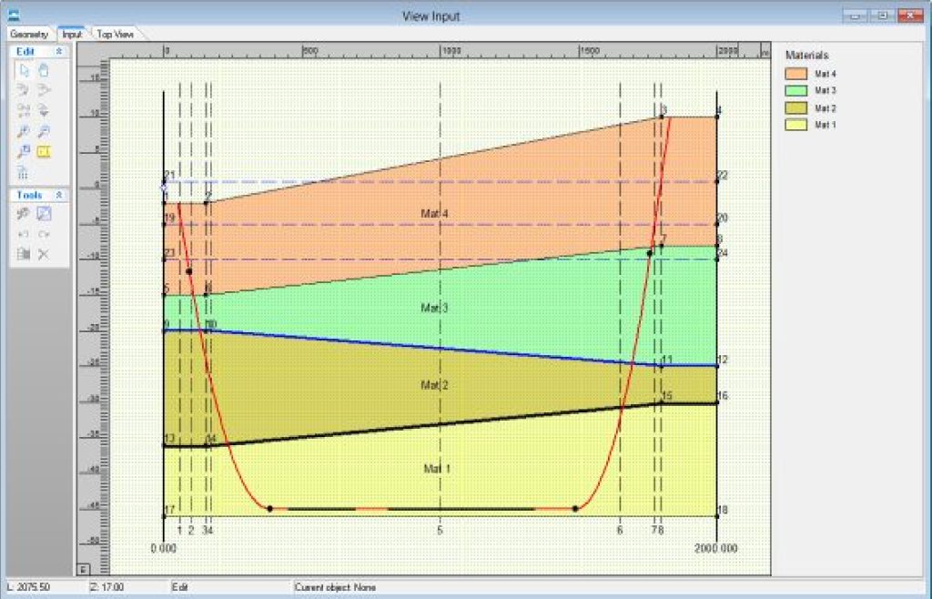
- Geometry and 3D pipeline configuration: The graphical user interface allows an easy and fast input of the soil layers. The upper soil layers can be designated as load for settlement calculation purposes. The three-dimensional pipeline configuration can be entered by a fast tabular input.
- Arching: In case of trenchless installation, D-Geo Pipeline applies a reduced neutral soil load to incorporate the effect of arching. The amount of reduction depends on the installation method, the depth of the pipeline, diameter and the soil properties.
- Pipe stress analysis for horizontal directional drilling installation: D-Geo Pipeline calculates the stresses in the pipeline during the installation stages in both axial and tangential direction. In a comprehensive report a stress verification is given for each pipeline material used.
- Advanced calculation of settlements: Vertical displacement of soil below the pipeline that occurs after installation is an important factor in assessing the stresses in the pipeline. Pipeline settlement may be entered manually if the vertical settlements are available. For more accurate results, D-Geo Pipeline can use the D-Settlement computer program without additional input.
- Advanced pipeline stress analysis: For advanced pipe stress analyses special programs need to be used. These programs need an advanced set of soil mechanical parameters, provided by D–Geo Pipeline . The programs will generate a complete spring model around the pipeline for further analyses.The soil mechanical parameters provided by D-Geo Pipeline are:
– neutral, passive and reduced vertical soil load
– vertical and horizontal modulus of sub grade reaction
– ultimate vertical and horizontal bearing capacity
– neutral horizontal soil load
– vertical displacement
– maximum axial friction
– friction displacement.
D-Geo Pipeline interacts with other tools:
- D-Settlement for analyses and import of settled geometry
- D-Geo Stability for slope stability analysis
How to get D-Geo Pipeline?
Service Packages
The current version is available by purchasing a Service package. You can order a Service package via our Sales Service team (software@deltares.nl).
The software can be downloaded via our Download portal. You don’t need a license file to do this. You can use the software in Demo mode without a license file. By purchasing a Service package you will receive a license file to unlock full functionality (according to purchased package). Our Sales Service team will provide you with instructions on how to get the software working with a license file.
D-Geo Pipeline is available in the following packages:
Full
Educational package
The Educational package is the same as the Full package, but available at a reduced price.
Please contact our Sales Service team for more information.
Online Software
You can also use our Geotechnical software products via the internet (Software as a Service – SaaS), on subscription basis. For more information, please see Online Geotechnical Software.
Price list
For the price list 2025, click here.